Standard filament printing is slow and expensive for large parts. You need a better way to scale up production without losing precision or breaking the bank.
Pellet 3D printing systems1 replace filaments with raw granules, using a screw extruder2 for higher output. The architecture combines robust motion systems, precise thermal zones, and advanced control logic to enable rapid, large-scale manufacturing with industrial-grade materials3.
I will walk you through the technical details. I want to show you exactly how these machines work from the inside out so you can understand their value.
Core Components of a Pellet Extrusion 3D Printer?
You might wonder what makes these machines different from standard desktop printers. The difference lies in the industrial hardware required to handle heavy loads.
A pellet printer consists of a hopper, a screw extruder, heating zones, a heavy-duty motion gantry, and a print bed. These components work together to melt raw plastic granules and deposit them accurately at high speeds.
The Anatomy of Industrial Printing
At CHENcan CNC, we build machines that last. The core components of a pellet system are much heavier than a standard printer. The extruder head alone can weigh ten times more than a filament print head. This means the rest of the machine must be stronger to support it.
Here is a breakdown of the main systems:
| Component | Function | Why it matters |
|---|---|---|
| Hopper | Stores raw pellets. | Feeds the system continuously for long prints. |
| Screw Extruder | Pushes and melts plastic. | Provides high flow rates for fast printing. |
| Motion System | Moves the head (X/Y/Z). | Determines the accuracy of the part geometry. |
| Build Plate | The surface for printing. | Ensures the part sticks and stays flat. |
Integration is Key
These parts cannot work alone. The controller must talk to the motor drivers, the heaters, and the sensors all at once. If the motion system moves too fast for the extruder, the print will have gaps. If the extruder pushes too much plastic, the print will be messy. We focus on integrating these systems so they act as one unit.
Screw Extruder Design and Material Feeding Mechanics?
Feeding material consistently is the hardest part of pellet printing. Poor feeding causes gaps in your final product.
The screw extruder acts like an injection molding machine. It rotates to transport pellets from the hopper, compress them, and force the molten plastic out of the nozzle with high pressure.
Why the Screw Design Matters
I have seen many generic extruders fail because they cannot maintain pressure. At CHENcan, we designed our own spiral extrusion head. We did not just buy off-the-shelf parts. We upgraded the screw geometry to handle different types of plastic better.
The Three Zones of a Screw
A proper screw has three distinct sections:
- Feed Zone: This pulls the cold pellets into the barrel. The channels here are deep to grab as much material as possible.
- Compression Zone: The channel depth gets shallower here. This squeezes the pellets, removing air and forcing them against the hot barrel walls.
- Metering Zone: This is the final stage. It ensures a steady, consistent flow of fully melted plastic out of the nozzle.
Solving the Air Bubble Problem
One big issue with pellets is trapped air. If air gets into the melt, your part will have bubbles. Our upgraded screw design compresses the material tightly to push air back out of the feed throat. This results in a solid, dense part that is much stronger than a standard 3D print.
Thermal Zones and Melt Stability Control?
Melting plastic unevenly ruins the structural integrity of the part. You cannot afford weak layers in industrial parts.
Precise thermal control involves multiple heating zones along the barrel. This ensures the plastic melts gradually and uniformly before it reaches the nozzle, preventing clogging and degradation.
The Importance of Gradual Heating
You cannot just blast the plastic with heat all at once. If you do, the outside melts while the inside stays solid. This causes clogs. We use a 3-stage heating system on our extruders. This allows us to control the temperature much more precisely.
How 3-Stage Heating Works
- Zone 1 (Rear): This is warm, but not hot. It softens the pellets so the screw can grip them.
- Zone 2 (Middle): This is the main melting zone. The plastic turns from solid to liquid here.
- Zone 3 (Nozzle): This zone sets the final extrusion temperature. It ensures the plastic is the right viscosity to flow onto the bed.
PID Control Loops
We use PID (Proportional-Integral-Derivative) controllers for each zone. The controller reads the temperature hundreds of times a second. If the temperature drops even one degree, it adds power. If it gets too hot, it cuts power. This keeps the melt stable. Stable heat means the layers bond together perfectly.
Motion Systems for High-Mass, High-Speed Deposition?
Moving a heavy extruder head quickly creates vibration. Vibration kills surface finish and dimensional accuracy.
High-mass printing requires a rigid gantry, high-precision guide rails, and powerful servo motors. These systems handle the inertia of the heavy extruder while maintaining smooth, accurate movements.
Handling the Weight
Our pellet extruder is heavy because of the motor, the screw, and the steel barrel. A standard belt system would stretch and bounce. That is why we use high-precision guide rails and ball screws or helical racks.
Servo Motors vs. Stepper Motors
Most small printers use stepper motors. They are cheap, but they can lose steps if they hit a bump. We use servo transmission systems.
- Feedback Loop: Servos have encoders. The motor tells the computer exactly where it is.
- Torque: Servos have high torque at high speeds. They can accelerate the heavy head quickly.
- Smoothness: Servos run smoother than steppers, which reduces the "ringing" marks on the surface of the print.
Structural Rigidity
The frame must be stiff. If the frame twists, the nozzle moves out of place. We use heavy steel gantries (metal cutting types) for our machines. This makes the entire mechanical design more stable. You can print fast without the machine shaking across the floor.
Firmware, Control Logic, and Process Synchronization?
Hardware is useless without a brain to control it. The printer needs to know exactly when to push plastic and when to stop.
The firmware synchronizes the rotation of the extrusion screw with the movement of the gantry. This ensures the flow rate matches the print speed perfectly for consistent line width.
The Challenge of Lag
In a filament printer, when you stop the motor, the flow stops almost instantly. In a pellet printer, there is a lot of molten plastic under pressure. It wants to keep oozing out. The firmware has to predict this.
Advanced Flow Algorithms
The control logic we use calculates the pressure inside the barrel. When the print head slows down for a corner, the screw must slow down before the corner. If it waits until the corner, you get a blob.
- Linear Advance: This feature predicts the pressure needed at different speeds.
- Look-ahead: The controller reads the G-code lines ahead of time to plan the speed changes.
Retraction Strategies
Retraction is pulling the material back to stop the flow. You cannot pull molten plastic back easily. Instead, we reverse the screw rotation briefly. This relieves the pressure instantly. The firmware manages this reversal speed and duration to prevent stringing between parts.
Flow Rate Calibration and Process Parameter Tuning?
Setting up a print job is not a guessing game. Wrong settings lead to blobs, strings, and failed prints.
Flow rate calibration involves testing the extruder RPM against the travel speed. You must tune parameters like layer height, extrusion width4, and temperature to match the specific material properties.
The Math of Extrusion
You need to balance the volume of plastic coming out with the speed of the machine.
Formula: Volume = Layer Height × Line Width × Speed
If you change the layer height from 1mm to 2mm, you need twice as much plastic. We have to adjust the screw RPM to match.
Tuning for Different Materials
Every material flows differently.
- PLA: Flows easily, needs less pressure.
- ABS: More viscous, needs higher heat and pressure.
- Glass-Filled Composites: These are abrasive and thick. They need higher torque from the screw.
Steps for Calibration
- RPM Test: We run the screw at a set RPM and weigh the output for one minute.
- Line Width Test: We print a single line and measure the width with calipers.
- Multiplier Adjustment: We adjust the "flow multiplier" in the software until the measured width matches the design width. We provide full-process customization and parameter optimization for our clients so they do not have to struggle with this alone.
Toolhead Modularity and Multi-Axis Configurations?
Sometimes a simple 3-axis printer is not enough. You might need to print complex shapes with overhangs.
Modular toolheads allow you to switch nozzle sizes or extruder types. Multi-axis configurations, like 5-axis systems, let you print on curved surfaces and reduce the need for support structures.
Changing Nozzles
One size does not fit all. Sometimes you need a 3mm nozzle for a huge boat hull. Sometimes you need a 0.8mm nozzle for a detailed mold. Our design allows for quick changes. You can unbolt the nozzle and screw in a new one.
The Power of 5-Axis
We are experts in 5-axis machining centers, so we applied that to printing. A standard printer builds flat layers. A 5-axis printer can tilt the tool.
- No Supports: You can print an overhang by tilting the part or the head.
- Strength: You can align the layers with the stress lines of the part. This makes the part stronger.
- Cladding: You can print onto an existing curved surface.
Hybrid Systems
We also offer hybrid machines. You can have a pellet extruder and a milling spindle on the same machine. You print the part slightly oversized, then the spindle comes in and machines it to the exact tolerance.
System Constraints That Limit Print Accuracy?
No machine is perfect, and pellet printing has limits. Ignoring these limits results in parts that do not fit together.
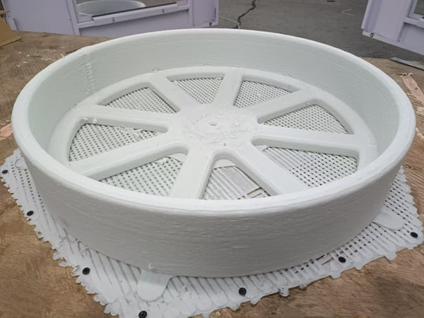
The main constraints are the size of the nozzle and the heat retention of the large bead. Large nozzles cannot print fine details, and thermal shrinkage5 affects the final dimensions.
The Minimum Feature Size
You cannot print a feature smaller than your nozzle. If you use a 2mm nozzle, you cannot print a sharp 0.5mm corner. It will always be rounded. This is a trade-off for speed. You get massive parts fast, but you lose fine detail.
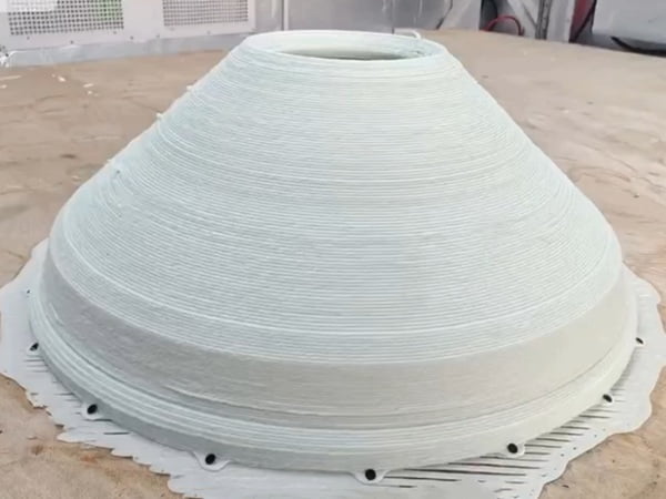
Thermal Shrinkage and Warping
Plastic shrinks when it cools. In pellet printing, you are laying down a lot of hot plastic.
- Heat Buildup: If you print small layers too fast, the previous layer does not cool down. The part becomes a blob.
- Warping: Large parts pull on the bed as they cool. This can lift the corners.
Managing Constraints
We design around these limits.
- Cooling Fans: We use powerful fans to cool the bead immediately after it is laid down.
- Heated Chambers: Keeping the air warm reduces the shock of cooling, which stops warping.
- Design Rules: We teach our clients to design parts with large radii and thick walls to suit the process.
Scaling Build Volume Without Sacrificing Reliability?
Making a machine bigger usually makes it less accurate. You need to scale up without losing the precision of smaller machines.
Scaling requires reinforcing the frame and using closed-loop control systems. We use heavy-duty steel structures and laser calibration to ensure the machine remains accurate across the entire build volume.
The Square-Cube Law
When you double the size of a machine, it becomes much heavier and more flexible. A small frame is naturally stiff. A large frame wants to sag. We use the same technology from our Gantry Machining Centers (metal cutting). These are designed to hold tons of weight. We use massive steel beams and columns.
Laser Interferometer Calibration
To ensure accuracy over a 5-meter or 10-meter length, we use laser testing equipment.
- Straightness: We measure if the rail is perfectly straight.
- Flatness: We measure if the bed is perfectly flat.
- Compensation: We map the errors and put them into the controller. The controller adjusts the motor position in real-time to correct for any tiny bend in the rail.
Reliable Long-Term Printing
A large print can take days. The machine cannot fail. We use high-quality cables and chains that can bend millions of times without breaking. We also use redundant sensors to detect if filament runs out or if a heater fails.
Design Considerations for Future Pellet 3D Printing Platforms?
The industry moves fast, and old designs become obsolete. We must look ahead to see what the next generation of printers needs.
Future designs will focus on faster cooling systems, automated material feeding, and smarter sensors. The goal is to make the machine run 24/7 with minimal human intervention.
AI and Monitoring
The next step is AI. Cameras will watch the nozzle. If the AI sees a defect, it will pause the machine or adjust the settings automatically. We are already looking into these technologies.
Automated Material Handling
Right now, you have to pour pellets into the hopper. Future systems will have vacuum loaders that suck pellets from a large silo directly to the extruder. This allows for non-stop production.
Higher Materials
We are seeing a demand for higher-temperature materials like PEEK and PEI for aerospace. This requires hotter chambers and liquid-cooled extruders. We are constantly upgrading our R&D to handle these super-plastics. We want to help our clients in aerospace and automotive stay ahead of the curve.
Conclusion
Pellet printing changes manufacturing. With CHENcan’s robust screw design, 3-stage heating, and servo motion control, you get speed and quality. It is the future of large-scale production.
Explore how Pellet 3D printing systems can enhance production efficiency and reduce costs. ↩
Learn about the mechanics of screw extruders and their role in high-output 3D printing. ↩
Discover the types of industrial-grade materials that can be used for robust 3D printing. ↩
Learn about the impact of extrusion width on the quality and strength of printed parts. ↩
Learn about thermal shrinkage and its effects on the final dimensions of 3D printed parts. ↩